
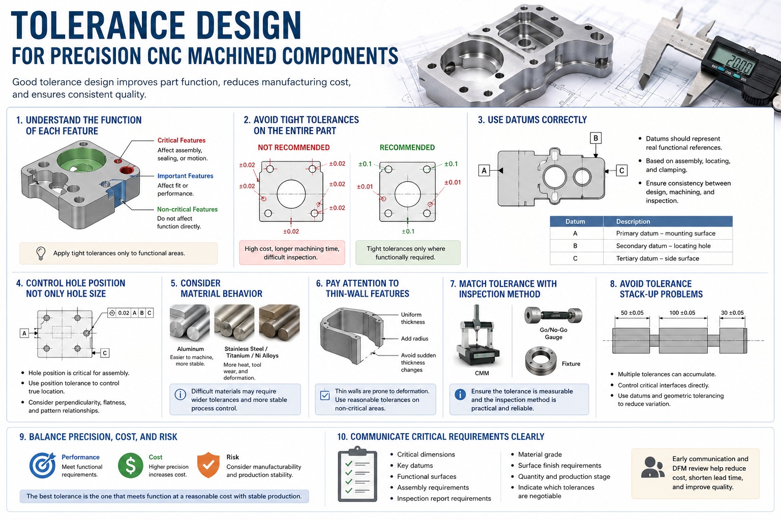
Tolerance design is one of the most important factors in precision CNC machining. It directly affects manufacturing cost, inspection difficulty, lead time, and final part performance.
For many engineered components, the problem is not that the tolerance is too loose. The real problem is that tight tolerances are applied to too many features without a clear functional reason. This can make a part more expensive, more difficult to manufacture, and more risky to inspect.
Good tolerance design does not mean making every dimension extremely precise. It means defining the right tolerance for the right feature based on function, assembly, material behavior, and production stability.
This article explains practical tolerance design principles for precision CNC machined components.
1. Understand the Function of Each Feature
Before defining tolerances, engineers should first understand the function of each feature.
Different features have different levels of importance. Some dimensions directly affect assembly, sealing, bearing alignment, or motion control. Others may only define external shape, weight reduction, or clearance.
For example:
- Bearing seats may require tight diameter and roundness control
- Sealing surfaces may require both dimensional and surface finish control
- Mounting holes may require accurate position tolerance
- Non-critical outer profiles may allow wider general tolerance
- Internal pockets may not need tight dimensional control if they do not affect function
The key question is:
Does this tolerance directly affect the part’s function?
If the answer is no, a standard or wider tolerance may be more appropriate.
2. Avoid Applying Tight Tolerances to the Entire Part
One of the most common causes of high machining cost is applying tight tolerances globally.
When a drawing specifies very tight general tolerances for all dimensions, the supplier must treat even non-critical features as precision features. This increases machining time, inspection workload, tool control requirements, and scrap risk.
For precision CNC parts, tight tolerances should be limited to functional areas such as:
- Mating interfaces
- Datum surfaces
- Precision bores
- Threaded or dowel holes
- Sealing surfaces
- Sliding or rotating features
- Critical assembly dimensions
For non-critical areas, general machining tolerances are usually sufficient.
This approach helps reduce cost while keeping the important features under control.
3. Use Datums Correctly
Datums are essential for controlling how a part is measured, assembled, and machined.
A datum should represent a real functional reference, not just a random surface on the drawing. Poor datum selection can create confusion between design intent, machining setup, and inspection results.
Good datum selection should consider:
- How the part is assembled
- Which surfaces contact other components
- How the part will be located during inspection
- How the part can be clamped during machining
- Which features need positional relationship control
For example, if a part is mounted using a flat base surface and two dowel holes, those features are often good candidates for datum references.
Correct datum design helps improve consistency between design, manufacturing, and inspection.
4. Control Hole Position Instead of Only Hole Size
For many CNC machined components, hole location is more important than hole diameter.
A hole may have an acceptable diameter, but if its position is inaccurate, the part may still fail during assembly. This is especially important for mounting plates, brackets, housings, fixtures, and aerospace components.
Instead of relying only on linear dimensions, engineers should consider using geometric tolerance control for critical hole patterns.
Important controls may include:
- Position tolerance
- Perpendicularity
- Flatness of mounting surfaces
- True position relative to datums
- Pattern relationship between holes
Good hole tolerance design helps ensure that the part fits correctly during assembly.
5. Consider Material Behavior
Different materials behave differently during machining.
Aluminum is generally easier to machine and more dimensionally stable under normal conditions. Stainless steel, titanium, nickel alloys, and other special metals may create more machining heat, tool wear, residual stress, and deformation.
For difficult materials, overly tight tolerances can significantly increase cost because the machining process must be more carefully controlled.
Material behavior may affect:
- Tool deflection
- Thermal expansion
- Residual stress release
- Thin-wall distortion
- Surface finish stability
- Inspection repeatability
When designing tolerances for special metals, engineers should consider not only the final dimension, but also the difficulty of maintaining that dimension during production.
6. Pay Attention to Thin-Wall Features
Thin-wall CNC machined parts require special tolerance consideration.
Thin walls are more likely to deform during clamping, cutting, heat buildup, and stress release. Even if the machine tool is accurate, the part itself may move during or after machining.
For thin-wall components, engineers should avoid applying unnecessarily tight tolerances to flexible areas unless functionally required.
Useful design practices include:
- Keeping wall thickness as uniform as possible
- Avoiding sudden changes in section thickness
- Adding radii at internal corners
- Allowing reasonable tolerance on non-critical thin-wall areas
- Discussing machining sequence with the supplier early
If high precision is required on thin-wall structures, additional fixtures, semi-finishing, stress relief, or final finishing operations may be needed. These steps increase cost, so they should be planned carefully.
7. Match Tolerance with Inspection Method
A tolerance should be measurable.
If a tolerance is specified too tightly but the inspection method is unclear or impractical, it can create disputes between the customer and supplier. This is especially true for complex surfaces, deep features, thin walls, and freeform geometry.
Before finalizing a drawing, engineers should consider:
- Can this feature be measured reliably?
- Is CMM inspection required?
- Is a gauge or fixture needed?
- Is the surface accessible for measurement?
- What is the acceptable inspection standard?
- Should critical dimensions be listed clearly in the inspection report?
For precision components, tolerance design and inspection planning should be considered together.
8. Avoid Tolerance Stack-Up Problems
Tolerance stack-up happens when multiple dimensions accumulate variation across an assembly.
Even if each individual part is within tolerance, the final assembly may still have fit or alignment problems if the tolerance chain is not properly controlled.
To reduce tolerance stack-up, engineers should:
- Define functional datums clearly
- Control critical interface dimensions directly
- Avoid unnecessary chained dimensions
- Use geometric tolerancing where appropriate
- Identify the most important assembly relationships
- Review tolerance accumulation during the design stage
Good tolerance stack-up control can reduce assembly problems and improve product reliability.
9. Balance Precision, Cost, and Risk
Tighter tolerances are not always better.
In CNC machining, every tolerance decision affects cost and risk. A tighter tolerance may require more careful programming, slower machining, higher-grade tooling, additional inspection, and more experienced operators.
A practical tolerance strategy should balance three factors:
- Functional performance
- Manufacturing cost
- Production stability
For prototypes, tighter tolerances may sometimes be acceptable to validate performance. For production parts, tolerance design should be optimized for repeatability and cost control.
The best tolerance is not the tightest tolerance. It is the tolerance that reliably supports the part’s function at a reasonable manufacturing cost.
10. Communicate Critical Requirements Clearly
Clear communication between the customer and supplier is essential.
When requesting a quote for precision CNC machined components, it is helpful to clearly identify:
- Critical dimensions
- Key datum features
- Functional surfaces
- Assembly requirements
- Inspection report requirements
- Material grade
- Surface finish requirements
- Quantity and production stage
If some tolerances are negotiable, this should also be communicated. A capable supplier may be able to suggest tolerance adjustments that reduce cost without affecting performance.
Early DFM review can prevent unnecessary machining cost and reduce the risk of manufacturing problems later.
Conclusion
Tolerance design is not only a drawing requirement. It is a major factor in manufacturability, cost control, inspection reliability, and final product performance.
For precision CNC machined components, engineers should apply tight tolerances only where they are functionally necessary, use clear datum structures, control critical hole positions, consider material behavior, and match tolerance requirements with practical inspection methods.
Good tolerance design helps customers reduce machining cost, shorten lead time, and improve production stability while maintaining the required engineering performance.
At Nova Special Metals, we support precision CNC machining of titanium, nickel alloys, tungsten, molybdenum, tantalum, niobium, and other special metals. By reviewing drawings, tolerances, material requirements, and inspection needs early, we help customers improve manufacturability and reduce unnecessary production risk.