
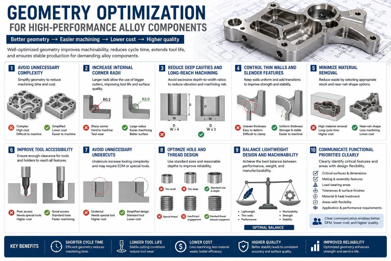
High-performance alloys are used in demanding applications where strength, heat resistance, corrosion resistance, fatigue performance, or weight reduction is critical. Common examples include titanium alloys, nickel-based superalloys, cobalt alloys, tungsten, molybdenum, tantalum, and niobium.
These materials are valuable, but they are also more difficult to machine than standard aluminum or mild steel. Tool wear, heat buildup, vibration, deformation, and long cycle time can all increase manufacturing cost.
For this reason, geometry optimization is one of the most effective ways to improve manufacturability. A well-designed geometry can reduce machining time, improve tool life, lower scrap risk, and make production more stable.
Geometry optimization does not mean weakening the part. It means improving the shape so that the component can meet its engineering function while being easier, safer, and more cost-effective to manufacture.
1. Avoid Unnecessary Complexity
Complex geometry usually increases machining cost.
For high-performance alloys, this cost impact is even greater because these materials often require slower cutting speeds, stronger tooling, and more stable setups. Features that may be acceptable in aluminum can become expensive or risky in titanium, Inconel, or refractory metals.
Designers should review whether each complex feature has a clear function.
Common cost-increasing features include:
- Deep pockets
- Narrow slots
- Sharp internal corners
- Undercuts
- Long thin ribs
- Complex 3D surfaces
- Hidden internal features
- Very small holes or grooves
If a feature does not affect function, assembly, strength, or weight requirement, it should be simplified where possible.
A simpler geometry usually means shorter cycle time, easier inspection, and better production repeatability.
2. Increase Internal Corner Radii
Sharp internal corners are difficult to machine with standard rotating tools.
In CNC milling, internal corners are created by the radius of the cutting tool. If the drawing requires a very small internal radius, the supplier may need to use a smaller tool. Smaller tools are weaker, remove material more slowly, and are more likely to vibrate or break.
For high-performance alloys, this problem becomes more serious because cutting forces and heat are higher.
Increasing internal corner radii can help:
- Use larger and stronger tools
- Improve tool life
- Reduce machining time
- Reduce vibration
- Improve surface quality
- Lower tool breakage risk
Where possible, internal corner radius should be designed larger than the minimum functional requirement.
This is one of the simplest and most effective DFM improvements for alloy components.
3. Reduce Deep Cavities and Long-Reach Machining
Deep cavities are expensive to machine, especially in hard or heat-resistant alloys.
Long-reach tools are less rigid and more prone to deflection, vibration, and poor surface finish. To maintain accuracy, the machining process may need to use slower feeds, lighter cuts, and multiple finishing passes.
Designers should avoid excessive depth-to-width ratios where possible.
Better design options include:
- Reducing pocket depth
- Increasing pocket width
- Opening one side of the cavity if function allows
- Using larger corner radii
- Avoiding narrow deep channels
- Designing better tool access
If a deep cavity is required, it should be clearly identified as a critical functional feature. Otherwise, reducing cavity depth can significantly lower machining cost.
4. Control Thin Walls and Slender Features
Thin-wall structures are common in aerospace, medical, and lightweight industrial components. However, they are difficult to machine accurately.
Thin walls can deform during clamping, cutting, heat generation, and stress release. Even if the CNC machine is highly accurate, the part itself may move during machining.
For high-performance alloys, thin-wall machining may require special fixtures, multiple process steps, stress relief, and careful cutting strategy.
Good geometry practices include:
- Keeping wall thickness as uniform as possible
- Avoiding sudden thickness transitions
- Adding radii at wall intersections
- Avoiding extremely long unsupported walls
- Adding temporary support features when possible
- Discussing machining sequence early with the supplier
Thin-wall geometry should be optimized for both weight reduction and production stability.
5. Minimize Material Removal
High-performance alloys are often expensive in raw material cost. Machining away a large amount of material also increases cycle time and tool consumption.
If a part is machined from a large billet and most of the material is removed, the total cost can become very high.
Designers should consider whether the geometry can be optimized to reduce material waste.
Possible approaches include:
- Selecting a better raw stock size
- Using near-net-shape forging where suitable
- Considering plate, bar, tube, or preform options
- Reducing unnecessary solid sections
- Using assembled structures where technically acceptable
- Optimizing blank size before machining
For titanium, Inconel, tungsten, molybdenum, and tantalum components, reducing material removal can create major cost savings.
6. Improve Tool Accessibility
A part should be designed so that cutting tools can access important features efficiently.
Poor tool access may require special tools, multiple setups, 5-axis machining, EDM, or secondary operations. These additional processes increase cost and lead time.
To improve tool accessibility, designers should consider:
- Can the tool reach the feature directly?
- Is there enough clearance for the tool holder?
- Are there hidden surfaces that require special angles?
- Can multiple features be machined from the same setup?
- Are small tools required only because access is too restricted?
Better tool access usually means faster machining and lower risk.
For high-performance alloys, this is especially important because stable cutting conditions are critical for tool life and dimensional accuracy.
7. Avoid Unnecessary Undercuts
Undercuts often require special tools or additional machining operations.
In some designs, undercuts are functionally necessary for clearance, locking, sealing, or assembly. However, unnecessary undercuts can make a part much more expensive.
Undercuts may require:
- Custom form tools
- T-slot cutters
- Extra setups
- EDM
- Manual finishing
- More complex inspection
Where possible, undercuts should be removed, simplified, or replaced with easier-to-machine geometry.
If an undercut is necessary, it should be clearly marked and discussed with the supplier during the DFM review stage.
8. Optimize Hole and Thread Design
Small holes, deep holes, and special threads can increase machining difficulty.
For high-performance alloys, drilling and threading require careful control because tool wear, heat buildup, and chip evacuation can become major problems.
Designers should use standard hole and thread specifications whenever possible.
Cost-effective practices include:
- Avoiding very small holes unless required
- Reducing excessive hole depth
- Using standard thread sizes
- Avoiding blind holes that are too deep
- Allowing reasonable thread engagement length
- Providing enough clearance for tapping or thread milling
- Avoiding holes located too close to thin walls or edges
Good hole and thread design can reduce tool breakage, improve reliability, and shorten machining time.
9. Balance Lightweight Design and Machinability
Many high-performance alloy components are designed for weight reduction. This is common in aerospace structures, robotics, racing components, medical instruments, and advanced equipment.
However, aggressive lightweight design can create machining problems if not carefully controlled.
Over-optimized lightweight geometry may result in:
- Very thin walls
- Long ribs
- Deep pockets
- High material removal rate
- Difficult clamping
- Distortion after machining
- Expensive inspection
The best design is not always the lightest possible geometry. The best design is one that achieves the required weight, strength, and stiffness while remaining manufacturable.
A practical lightweight component should balance:
- Structural performance
- Machining stability
- Fixture design
- Inspection feasibility
- Production cost
Early DFM review can help avoid expensive redesign later.
10. Communicate Functional Priorities Clearly
Geometry optimization works best when the supplier understands which features are truly critical.
When requesting a quote for high-performance alloy components, it is helpful to identify:
- Critical load-bearing areas
- Mating and assembly surfaces
- Sealing surfaces
- Thin-wall or lightweight areas
- Critical holes and threads
- Surfaces requiring tight tolerance
- Areas where geometry can be adjusted
- Application background
If certain features are flexible, the supplier may suggest easier-to-machine alternatives. These small changes can often reduce cost without affecting performance.
Clear communication allows design intent and manufacturing reality to be aligned.
Conclusion
Geometry optimization is a key part of Design for Manufacturing for high-performance alloy components.
By simplifying unnecessary complexity, increasing internal radii, reducing deep cavities, controlling thin walls, minimizing material removal, improving tool access, avoiding unnecessary undercuts, and optimizing holes and threads, engineers can significantly improve machinability and production stability.
For titanium, nickel alloys, cobalt alloys, tungsten, molybdenum, tantalum, niobium, and other special metals, good geometry design can reduce cost while maintaining the required engineering performance.
At Nova Special Metals, we support precision machining of high-performance alloy components for demanding industrial applications. Through early DFM review, material understanding, and process planning, we help customers improve manufacturability, reduce production risk, and achieve more stable manufacturing results.