
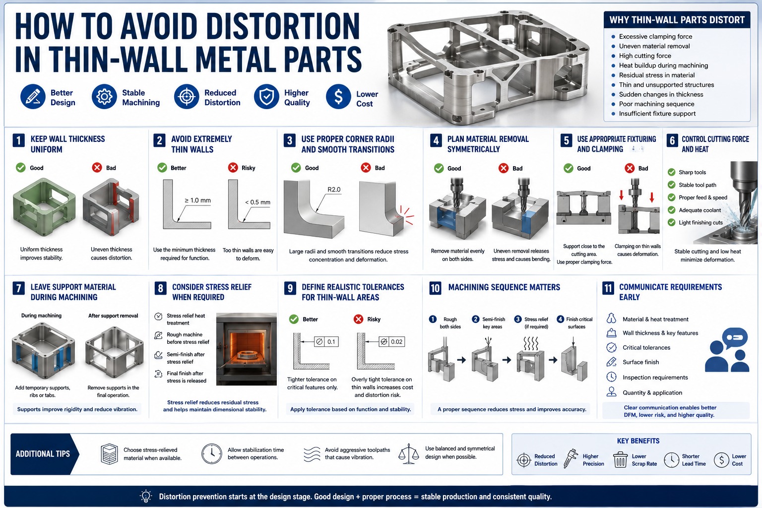
Thin-wall metal parts are widely used in aerospace, medical devices, robotics, semiconductor equipment, precision instruments, and lightweight industrial structures. These components are often designed to reduce weight while maintaining strength, stiffness, and functional performance.
However, thin-wall parts are also difficult to machine accurately. During CNC machining, they may deform because of clamping force, cutting force, heat buildup, internal material stress, or uneven material removal. Even if the CNC machine itself is accurate, the part can still move, bend, or twist during production.
For titanium, stainless steel, nickel alloys, aluminum alloys, and other high-performance materials, distortion control must be considered early in the design and process planning stage.
This article explains practical ways to avoid distortion in thin-wall metal parts and improve machining stability.
1. Understand Why Thin-Wall Parts Distort
Thin-wall distortion is usually caused by a combination of design, material, and machining factors.
Common causes include:
- Excessive clamping force
- Uneven material removal
- High cutting force
- Heat buildup during machining
- Residual stress inside the raw material
- Thin and unsupported wall sections
- Sudden changes in wall thickness
- Poor machining sequence
- Insufficient fixture support
Thin-wall parts have lower rigidity than solid components. When cutting force or clamping force is applied, the part may temporarily deform. After the tool or clamp is released, the part may spring back, causing dimensional error.
Understanding the distortion mechanism is the first step toward preventing it.
2. Keep Wall Thickness as Uniform as Possible
Uneven wall thickness is one of the most common causes of distortion.
When one area of the part is thick and another area is very thin, the part may release stress unevenly during machining. This can cause bending, twisting, or local deformation.
A better design should keep wall thickness as uniform as possible.
Good practices include:
- Avoiding sudden thickness changes
- Using smooth transitions between thick and thin sections
- Adding radii at wall intersections
- Avoiding isolated thin ribs
- Keeping lightweight pockets balanced
- Maintaining symmetrical geometry where possible
Uniform wall thickness improves structural stability and makes machining more predictable.
3. Avoid Extremely Thin Walls Unless Necessary
Thin walls reduce weight, but they also increase machining risk.
If a wall is designed thinner than functionally required, the part may become difficult to clamp, machine, inspect, and assemble. The supplier may need special fixtures, lighter cutting parameters, multiple finishing passes, or additional straightening operations.
This increases cost and lead time.
Before finalizing the design, engineers should ask:
- Is this wall thickness required for weight reduction?
- Can the wall be slightly thicker without affecting function?
- Is the wall strong enough during machining and assembly?
- Will the wall deform under clamping or cutting force?
- Is the tolerance realistic for this wall thickness?
For thin-wall metal parts, a small increase in wall thickness can sometimes greatly improve production stability.
4. Use Proper Corner Radii and Smooth Transitions
Sharp corners and sudden section changes can create stress concentration and machining instability.
In thin-wall parts, sharp internal corners may increase the risk of local deformation, cracking, vibration, or tool marks. They also force the supplier to use smaller tools, which are less rigid and more prone to vibration.
Better design practices include:
- Adding generous internal radii
- Using smooth transitions between walls and bases
- Avoiding sharp changes in wall height
- Avoiding narrow root sections
- Using fillets at rib intersections
- Reducing abrupt geometry changes
Smooth geometry helps distribute stress more evenly and improves machining stability.
5. Plan Material Removal Symmetrically
Uneven material removal can release internal stress and cause the part to bend.
For example, if a large amount of material is removed from only one side of a block, the remaining structure may deform as stress is released. This is especially important for aluminum, titanium, stainless steel, and nickel alloys.
A good machining strategy should remove material in a balanced way.
Possible methods include:
- Rough machining both sides before finishing
- Leaving uniform stock for final machining
- Using multiple roughing passes instead of one heavy cut
- Avoiding aggressive material removal from one side only
- Finishing critical surfaces after stress has been partially released
- Keeping the part supported during roughing and semi-finishing
Balanced material removal helps reduce warping and improves dimensional stability.
6. Use Appropriate Fixturing and Clamping
Clamping is a major factor in thin-wall part distortion.
If the clamping force is too high or applied in the wrong location, the part may deform during machining. When the clamp is released, the part may spring back and dimensions may fall out of tolerance.
Good fixture design should provide stable support without excessive force.
Useful practices include:
- Supporting thin walls close to the cutting area
- Avoiding direct clamping on flexible sections
- Using soft jaws or custom fixtures
- Distributing clamping force evenly
- Using vacuum fixtures where suitable
- Using sacrificial support structures if needed
- Checking part deformation after unclamping
For precision thin-wall parts, fixture design is often as important as CNC programming.
7. Control Cutting Force and Heat
High cutting force and heat buildup can distort thin-wall parts.
Difficult materials such as titanium and nickel alloys generate more cutting heat and require careful machining control. If cutting parameters are too aggressive, the part may vibrate, bend, or develop local thermal deformation.
To reduce machining distortion, suppliers may use:
- Sharp cutting tools
- Stable tool holders
- Lower radial engagement
- Proper feed and speed control
- Sufficient coolant delivery
- Step-by-step roughing and finishing
- Lighter finishing cuts
- Toolpath strategies that reduce vibration
The goal is to maintain stable cutting conditions and avoid excessive mechanical or thermal stress on the part.
8. Leave Support Material During Machining
For very thin or flexible parts, temporary support material can help maintain rigidity during machining.
Instead of machining the final thin-wall shape too early, the supplier may leave extra material, tabs, ribs, or support sections during roughing and semi-finishing. These supports are removed in the final operation.
This method can help:
- Improve rigidity during machining
- Reduce vibration
- Prevent wall movement
- Maintain dimensional accuracy
- Reduce scrap risk
Temporary support features should be considered during the DFM review stage, especially for complex thin-wall aerospace or precision equipment components.
9. Consider Stress Relief When Required
Some materials contain residual stress from rolling, forging, casting, heat treatment, or previous machining operations.
When material is removed, this stress may be released and cause distortion. For high-precision thin-wall parts, stress relief may be required before final machining.
Possible process approaches include:
- Stress-relief heat treatment
- Rough machining before heat treatment
- Semi-finishing before final finishing
- Allowing stabilization time between operations
- Final machining after stress release
- Selecting stress-relieved raw material when available
Stress relief adds cost, but it can reduce the risk of distortion, especially for precision thin-wall parts with tight tolerances.
10. Define Realistic Tolerances for Thin-Wall Areas
Tight tolerances on thin flexible areas can be difficult and expensive to maintain.
A thin wall may change shape slightly during clamping, machining, inspection, or even after release from the fixture. If very tight tolerances are applied to all thin-wall features, the manufacturing cost and scrap risk can increase significantly.
A better approach is to separate critical and non-critical areas.
For example:
- Critical assembly surfaces can have tighter tolerances
- Non-functional thin-wall surfaces can use wider tolerances
- Profile tolerance can be used where appropriate
- Datum references should reflect real assembly conditions
- Inspection method should be clearly defined
Realistic tolerance design helps reduce cost while keeping functional requirements under control.
11. Communicate Functional Requirements Early
Thin-wall distortion control requires close communication between design and manufacturing teams.
When requesting a quote, it is useful to provide:
- 2D drawings and 3D models
- Material grade
- Wall thickness requirements
- Critical tolerance areas
- Assembly function
- Surface finish requirements
- Heat treatment requirements
- Inspection requirements
- Expected production quantity
If some geometry, wall thickness, or tolerance areas are adjustable, this should be clearly communicated. A supplier with thin-wall machining experience may suggest design or process changes that reduce distortion risk.
Early DFM review is one of the most effective ways to avoid problems before production begins.
Conclusion
Distortion in thin-wall metal parts is not caused by one single factor. It is usually the result of geometry design, material stress, clamping force, cutting force, heat buildup, and machining sequence working together.
To reduce distortion, engineers should keep wall thickness uniform, avoid unnecessary thin sections, use smooth transitions, plan balanced material removal, apply proper fixturing, control cutting force and heat, leave temporary support material when needed, and define realistic tolerances.
For titanium, nickel alloys, stainless steel, aluminum alloys, and other high-performance metals, distortion control should begin at the design stage—not after machining problems appear.
At Nova Special Metals, we support precision machining of thin-wall and complex metal components for demanding industrial applications. Through early DFM review, material understanding, fixture planning, and process control, we help customers reduce distortion risk and improve manufacturing stability.